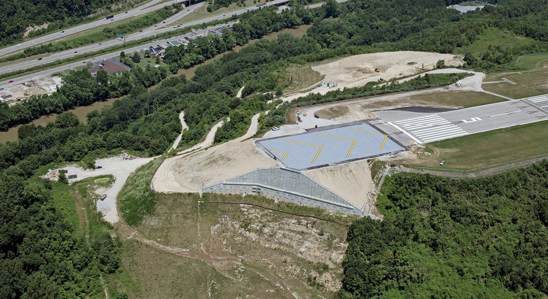
A photo shows the Yeager Airport with an 83-foot-tall, 400-foot-long reinforced retaining wall supporting the hillside beneath the restored EMAS system
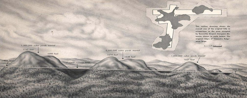
When construction began in 1944, demolition plans called for more than 2 million pounds of explosives, which were used to blow the tops off three adjoining mountains to create a level airfield. During construction, a pipeline built to the top of the site supplied the 2,500 gallons of fuel required each day as the blasted earth was dozed and compacted. The end result is an airfield mounted on sharply sloped hills 300 feet above the valleys of the Elk and Kanawha Rivers.
“In 1947, when the airport opened, the construction program was the second largest earth-moving project ever, behind only the Panama Canal,” explains Johanna Simon, senior engineer and instrumentation specialist at Schnabel Engineering. Originally named the Kanawha Airport, in 1985 it was renamed to honor General Chuck Yeager, a West Virginia native and the first person to break the sound barrier.
Needing EMAS
Beyond the name, the airport has undergone many expansions and modernizations, including terminal renovations in 1986, a concourse addition in 2001 and an Engineered Materials Arresting System (EMAS) added to the end of Runway 5, which was constructed in 2005 in response to updated FAA regulations.
“An EMAS is a specially designed safety system placed at the far end of a takeoff or landing zone where airports lack space for traditional safety areas,” notes Simon. “This is to protect against a runway excursion, which is an aircraft overrun.”
A properly designed and constructed EMAS will absorb the kinetic energy of a runway excursion aircraft in less space and time than a traditional safety area. Made as a bed of lightweight, crushable cellular cement blocks encased in a protective cover, according to FAA regulations, an effective EMAS system will fully arrest an aircraft when it enters the EMAS at 70 knots or less. To construct the EMAS system in Charleston, engineers had to extend the hillside below the runway. Doing so involved placing approximately 1 million cubic yards of fill in a two-part solution involving both a reinforced soil slope (RSS) and an unreinforced slope.
In January 2010, the EMAS at Yeager was put to the test when a U.S. Airways Express 50-seat regional jet rejected its takeoff, and the pilot was forced to bring the aircraft to an abrupt halt. Fortunately, it passed with flying colors. As designed, the EMAS crumpled under the plane’s weight, preventing the aircraft from plunging over the precarious edge at the end of the runway and saving the lives of nearly 40 passengers and crew. Certainly, that situation can be considered a success.
Slope Failure
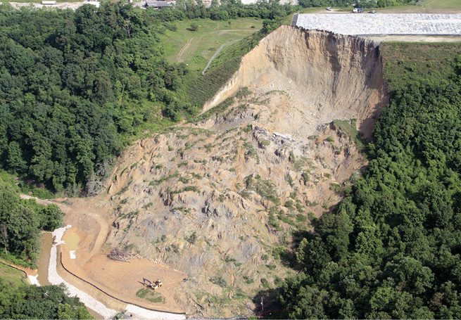
A separate situation in 2015 involving the 240-foot-high slope supporting the EMAS, however, was recognized legally as an engineering and construction failure in 2019.
“In March of 2015, after about eight years of service, the engineered slope beneath the EMAS failed,” says Simon. The collapse sent more than 540,000 cubic yards of debris down the hillside. A post-failure investigation revealed a fill-rock interface region composed of degraded sedimentary rock below the RSS as the culprit in the catastrophe that sent soil and rock sliding down the hill into a valley below, destroying a church and several homes as well as blocking Elk Two-mile Creek for a time. Schnabel’s scope focused on the aftermath and resolution.
“Schnabel was retained to stabilize the slope face, deconstruct the collapsed hillside, and engineer a long-term solution to support the EMAS area above,” explains Simon. “As the project manager for the reconstruction, I oversaw a team that designed a new vertical wall and backfill to bring the overrun area back up to runway grade. As part of this project, we specified a package of highly sensitive instrumentation to be incorporated into the wall and the supporting structures to monitor the performance of the system and detect any future movements in real-time.”
A Massive Wall
Developing a wall stout enough to hold up the side of a mountain and tall enough to reach the EMAS area above was the first challenge of the reconstruction process. The problem is a matter of pressure, primarily from the height of the backfill against the planned wall. After the rock and debris were safely cleared away during deconstruction, a working bench hewn from the mountainside was leveled at 860 feet. The structural solution had to support the hillside another 85 feet up the mountain to the EMAS area at an elevation of 945 feet. The solution turned out to be a massive retaining wall 400 feet long and 83 feet high at the center. Schnabel designed the new wall in two sections to control load magnitudes.
“The length and height of this wall meant backfilling it with traditional soil backfill methods would be challenging,” says Simon, revealing the project’s geotechnical complexity. “Tiebacks are anchoring the wall to the mountainside. However, the higher the wall goes, the less there is to tie to as the rock drops away from the wall. We designed the lower 25 feet to retain compacted soil as one section and backfilled the upper 55 feet of the wall with lightweight geofoam blocks as a second section.”
The lower wall section was secured to existing sandstone bedrock with rock-socketed steel piles and post-tensioned, tie-back anchors. The fill material was taken from the deconstructed and reprocessed remains of the failed RSS previously cleared from the site. Meanwhile, the remaining 55 feet incorporated a lightweight cellular material known as geofoam, a product most would describe as Styrofoam, which is actually a brand name rather than a material.
“Geofoam comes in massive 8-foot by 4-foot blocks made in varying densities,” notes Simon. Made from expanded polystyrene (EPS), geofoam is one of many applications for this rigid closed-cell foam material made from expanding polystyrene beads with air. Geofoam manufacturers produce the blocks in varying lengths and densities ranging from 2.2 psi to 18.6 psi. Large projects such as reconstructing the wall beneath the EMAS at Yeager often benefit from combining multiple engineered grades of geofoam to achieve the right balance of structural capacity and cost-effectiveness. “We created a tapered layering plan that uses the densest blocks at the bottom of the stack, decreasing in density as they went up, with a soil cap on top.”
Monitoring for Prevention
While the task of restabilizing the hillside was primarily engineering, for Simon there was added benefit in integrating her passion for instrumentation.
“Schnabel’s mandate from the client was to fix the problem and prevent it from ever happening again,” she says. “Before the collapse, the airport could tell from periodic land surveying that the RSS was settling. So, the collapse wasn’t a complete surprise. However, the airport wanted checks and balances built into the new solution to monitor it quantitatively. That’s where instrumentation comes in, which is an area of geotechnical engineering I specialize in.“I believe in monitoring with a purpose,” adds Simon. “That starts with the quantitative questions to be answered during and after construction, and designing an instrumentation package that fits those objectives.” For the airport, Schnabel, the deconstruction team and the reconstruction team at Orders Construction, the first question to answer was safety.
“Deconstructing the collapsed slope was a matter of emergency management,” notes Simon. “After the slope failure, what remained was a near-vertical, unstable soil face approximately 140 feet high. A temporary instrumentation system consisting of survey targets was installed at the crest of the vertical soil face to monitor possible movement during deconstruction as an early warning to workers while the soil wall was taken apart.”

The ongoing risk of further collapse was confirmed three months after the initial incident when a secondary failure of 10,000 cubic yards of material occurred in June 2015. Fortunately, that occurred just before deconstruction began, beneficially alleviating some of the downward pressure.
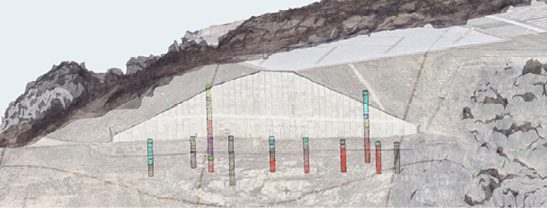
When all three phases of deconstruction were finally complete two years after the initial failure, the top priority was to ensure it couldn’t happen again. This meant preemptive, active monitoring going forward. The final instrumentation package involved 45 different sensors embedded into the finished work. That included eight inclinometers (ShapeArrays), five load cells, 12 strand meters, 18 strain gauges and two multiple-point borehole extensometers. Each provides ongoing structural loading data in various ways.
“The ShapeArrays monitor deflection in the retaining wall,” explains Simon. “Load cells on the tieback anchors monitor the amount of tension from the wall to the anchor and what type of load we’re seeing. The borehole extensometers will monitor settlement in the lower backfill behind the wall. Pairs of strain gauges were mounted on the tierods that run from the front face of the upper wall to the piles embedded in the mountainside to detect additional force on the upper wall.” Asked about lessons learned in selecting the right instrumentation package, Simon admits that as an engineer, turning over control of the instrumentation installation to the builders made specification tedious.
“Though I laid out the plans for the instrumentation system, when it came to installation and calibration, I had to sit on the sidelines and watch it happen,” she adds. “This meant being extremely precise in the design specifications. All the data was connected to the cloud using the sensemetrics platform, a sensor data-management solution now part of Bentley. Once the system was built, I also got involved in helping visualize the data for the airport.”
Empowering both owners and engineering partners with real-time data insights, Bentley’s sensemetrics was chosen for the ease of deployment, the range of sensors supported, and the software’s sensor data management and visualization capabilities.
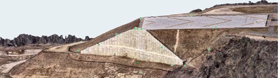
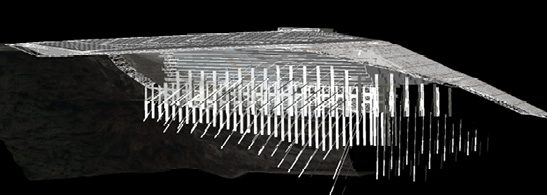
iTwin models show the geotechnical data collected during deconstruction as well as the sensor data providing real-time feedback and monitoring of the site.
“Sensemetrics visualizations help engineers and owners understand the monitored performance of an engineering asset in real-time, as things change,” continues Simon. “The values being monitored come directly from the design thresholds. Using a 3D modeling program called iTwin, we can visualize and analyze the incoming data in several ways. The airport mainly needs alerts if a portion of the structural system is not functioning as designed. The engineers monitoring the system no longer need to climb around the site to take measurements and then run calculations to understand the implication of those measurements. All of that is available immediately through the sensors and software.”
For Simon, the big takeaway in infrastructure instrumentation monitoring begins with reducing situational sensitivity. Roads, bridges, retaining walls and all sorts of additional structures that are subject to natural geotechnical forces can benefit from early detection and performance monitoring.
“Monitoring infrastructure with embedded sensors is about risk management,” finishes Simon. “In real-time, this protects the ‘boots on the ground’ workforce from exposure to potentially dangerous conditions during and post-construction. Long-term, as an asset ages, infrastructure owners can detect and resolve situational sensitivities before they become emergencies or worse.”


Sean Vincent O'Keefe
Sean Vincent O'Keefe is an architecture and construction writer who crafts stories and content based on 20 years of experience and a keen interest in the people who make projects happen; email: sean@sokpr.com.
Stormwater Interview with Robert Page, P.E., Vice President, HNTB
TriMet’s Banfield Type 1 Substation Replacement Project

February Issue 2026